Amiga demoscene for beginners
Part 0 - architecture overview
Before we will dive into code, it's good to get to know the machine we are going to work with.
Of course, we would like to be compatible with as many Amiga models as possible. Sure, you may have a maxed-out A1200 with 060 CPU, lots of RAM, and a fancy graphics card, and you can write something that will look nice on your machine, but that's not a setup majority of people have, so they wouldn't be able to experience your awesome production!
That's why we are going to target the most classic Amiga possible: the vanilla A500 rocking Kickstart 1.3 and 1MB of ram (512K + 512K trapdoor expansion card).
This will give us the possibility to run our code on pretty much anything (sorry, Amiga 1000 ₍ᐢ.‸.ᐢ₎).
OCS chipset
As you could deduce from the title, this series of posts is going to target the OCS. But what does it exactly mean?
OCS stands for Original Chip Set. It's a version of the Amiga chipset, that started its life with A1000, then (after some revisions) got implemented in A500 and A2000. Later it was reworked a bit for the Amiga 3000 and introduced as ECS, Enhanced Chip Set. In 1992 the last version of the chipset, AGA (Advanced Graphics Architecture) hit the market.
We are going to focus only on the first version of the chipset here, but don't worry, most of the time we will be able to run our code on ECS and AGA without any issues. OCS consists of a few important parts: custom chips and fast/chip/"slow" RAM sections. The diagram below represents the system architecture:
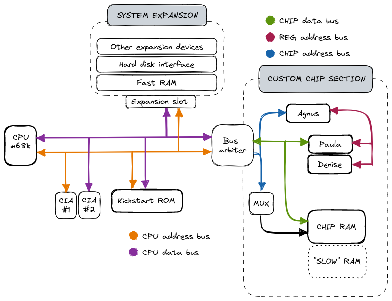
It's divided into two main sections - the realm of the CPU and a custom chip section. Before we'll get to the chipset itself, it's important to explain how the RAM works. As you can see, there are three types of it, living in different parts of the system. What's the difference?
Fast RAM - this is the memory that the custom chips can't use. Because of that, the CPU is free to access it at full speed at any given time (hence the name). It's optional, requiring an additional expansion memory card.
Chip RAM - onboard Amiga memory. It's shared by both the CPU and the custom chips. Theoretically, Motorola 68000 can access it during every other cycle, but in practice, custom chips are prioritized and can "steal" its cycles, as they deal with time-sensitive tasks like video refresh.
"Slow" RAM (also known as "pseudo fast" RAM) - this one is a bit tricky. In A1000 the Agnus chip could address only 512K of RAM. In early revisions of A500, it was replaced with "Fat Agnus" which still supported only 512K of chip RAM, but also allowed to add another 512K of memory that is neither chip RAM nor a true fast RAM.
Custom chips are the backbone of the Amiga system, taking most of the load off of the m68000 CPU to manage audio, video, and I/O. Let's take a look at some of the most useful features they provide, starting with the two coprocessors that live inside the Agnus chip.
Copper
It's a simple, yet powerful tool that gives you almost full control over the video system, via the feature called Copper lists. Copper list consists of a programmer-defined set of instructions that will be called once every frame, either during a vertical blanking period or when the beam hits a specific coordinate on the screen. For example, it's very commonly used for various palette modifications, look at this screenshot from a popular Amiga game "Shadow of the beast":
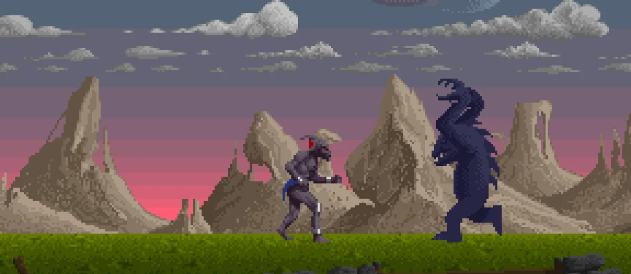
Do you see the blocky blue-pink gradient in the sky? In reality, the whole sky background is a solid color - but the Copper is programmed to change this one color every X lines mid-frame, which results in this nice, atmospheric sunset. Other example usages include modifying sound registers and setting up and starting Blitter (more about it in a minute).
So, how does it work?
At its core, Copper's "instruction set" is very simple, there are only three of them: MOVE, WAIT and SKIP.
MOVEmodifies the state of a given register. It can modify most of the Amiga special registers - for example,BPLXPTHandBPLXPTLwhich are responsible for setting up bitplanes.WAITtells Cooper to wait until the video beam reaches the specific coordinates on the screen. While it's waiting, it frees the bus.In the ideal world all our code runs fast enough our Copper instructions can be executed at the exact beam positions we want. In reality, sometimes this is not the case - maybe some calculations took longer than expected, maybe BIitter hogged the bus, and by the time Copper got to the instruction it was supposed to execute at the beginning of line 23, the beam has already reached line 24. What now? By default, Copper will just execute this instruction anyway. Sometimes this is not a big problem, like in our sky gradient example above, the world won't end if we change the color one line later. But oftentimes it's better to omit it altogether in a given frame. This is when the
SKIPcan aid us. It takes X and Y coordinates (just likeMOVE) and lets us skip the instruction that comes immediately after it if the video beam is already past them.
There are a few important Copper's limitations. One of them is that due to memory timings, in the absolute best-case scenario, we can execute one instruction every 8 pixels on the screen. Another thing we need to keep in mind is that it can't affect memory contents directly, only the registers. But, as mentioned above, we can use the Copper list to set up and run Blitter, which is another powerful tool at our disposal.
Blitter
This is Amiga's second coprocessor responsible for efficient DMA operations on big blocks of the chip RAM. It's estimated that it's around two times faster than m68k at copying memory, which is very useful for all sorts of graphics-related operations. Blitter has two main modes - line and block.
Line mode
In this mode Blitter can efficiently draw textured lines on the screen using the Bresenham's algorithm. The max length of one line is 1024 pixels. It's possible to draw simple shapes and fill them with color.
Block move mode
Blitter can quickly copy and move memory around. But block mode is much more than that - through utilizing its four DMA channels, called A, B, C ("source" channels), and D ("destination"), it can perform complicated logic operation all sources to compile the final image on the fly. Programming Blitter in this mode is a deep rabbit hole in itself, which we will explore in the future.
How the image is made
As demosceners, we need to know exactly how Amiga generates the picture. It's a bit complex process, but after getting into it, you'll realize it provides us a wide range of tools we can use to do some pretty sick stuff.
Display modes
In OCS, we have four "primary" modes:
- Low resolution, called lores. It supports 32 colors and for NTSC systems it's 320 x 200, and for PAL - 320 x 256.
- High resolution, hires mode. Drops to only 16 colors, but we get 320 x 400 (NTSC) or 640 x 256 (PAL).
- Remaining two are interlaced version of the previous ones. As you can imagine, the number of colors and vertical resolution stays the same, but the horizontal resolution is doubled.
Simple, right? Well... there's more! There are also two special modes - HAM (Hold and Modify) and EHB (Extra Half Brite). They provide the ability to display more colors (4096 for HAM and 64 for EHB), but they come with their quirks and constraints, which makes them not suitable for every effect. We will revisit them both in the future, since explaining how exactly HAM works deserves its own post.
Bitplanes and playfields
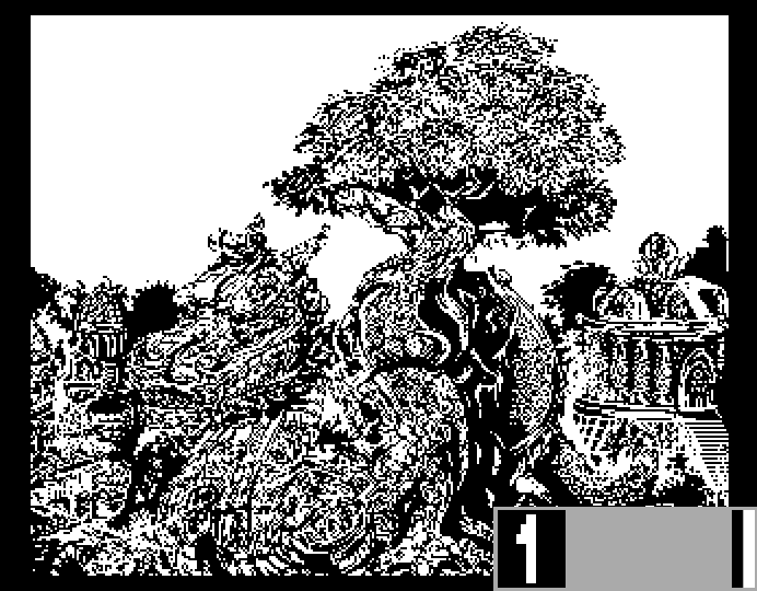
It will be easiest to explain with an example. Look:
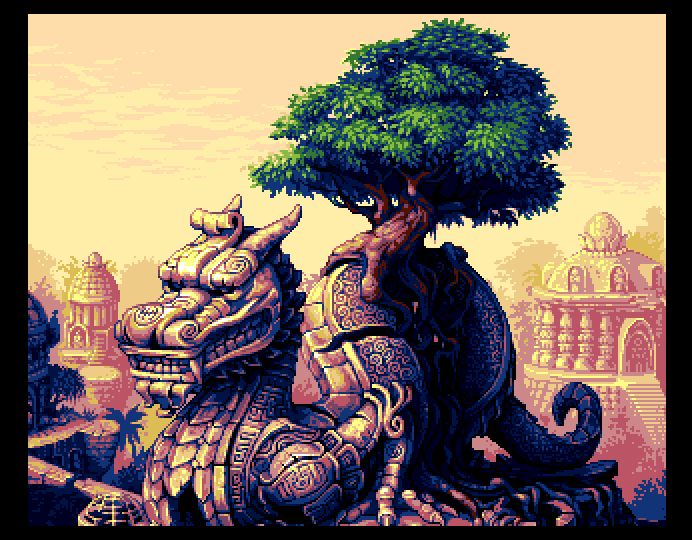
Its resolution is 320 x 256 and it uses 16 colors, so a standard lores PAL full-screen image. We are also going to use all five bitplanes. What are bitplanes? It's closely related to the depth of the image we want to display. Imagine five monochrome layers, placed on top of each other to form the full, colored picture. How?
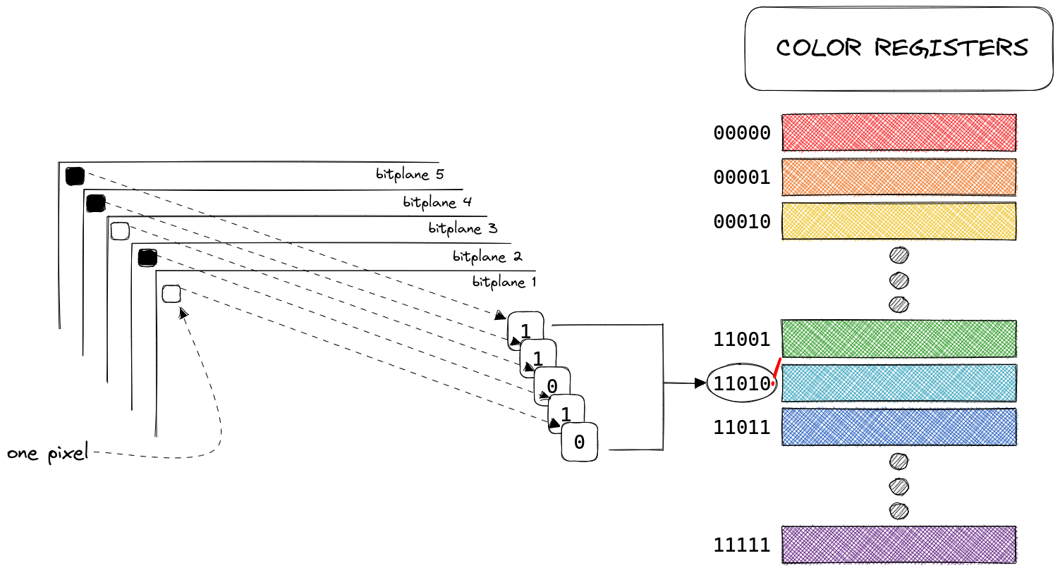
To determine the color of each pixel, Amiga fetches the value of this pixel on every bitplane and puts them together, to find the index of the color register that it's supposed to use.
The example below shows a hypothetical bitmap, with the value of the first pixel for each bitplane marked as either 1 (black square) or 0 (white square). After putting them together we get 11010 (0x1A) which is the index of the color register that holds the final color of this particular pixel. In our example, the pixel will be light blue.
GIF below illustrates how our picture will look if we reduce the number of displayed bitplanes:
Bitplanes are grouped into playfields. You can think of them as containers. It's possible to display one or two playfields at the same time. The latter scenario is called the Dual Playfield Mode. It creates two "layers" that can be manipulated separately. This mode is often used for games, where one playfield displays the actual game, while the second playfield, containing a status bar/icons/menus is overlaid on top of it. While using dual playfields, each of them can contain up to three bitplanes - one playfield contains bitplanes 1, 3, and 5, while the other 2, 4, and 6.
Sprites
Sprites are special entities, that live beyond the bounds of playfields and bitplanes. There are 8 available sprites, grouped by two, which means they have some shared attributes. Each sprite is 16 pixels wide and can have unlimited height. They can have up to three colors (+ transparency), and the palette is set per group, which means sprites 0 and 1 will share the same three colors, while sprites 2 and 3 will have their own set of colors and so on. Another thing that is specific for each sprite in a group is their display priority relative to playfields. The "Amiga Hardware Reference Manual" book uses the hand analogy to illustrate how it works and I think it's too cute not to share in its original form:
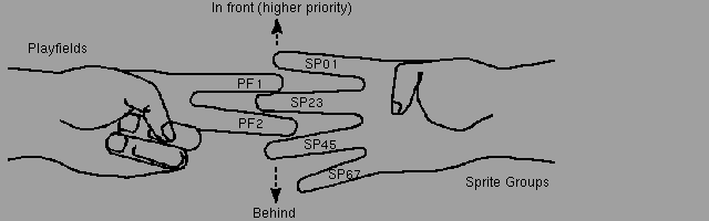
This default order can be modified by using the BPLCON2 register (which stands, of course, for "bitplane control register 2", and yes, there is also BPLCON1).
The sprite groups support a mode called "attached", where instead of two sprites, the whole group functions as one sprite. The maximum size stays the same, but each pixel uses four bits to address its color register (instead of the two bits used normally) which results in up to 15 possible colors (which are color registers used by sprites).
Scrolling
Each playfield can also be scrolled independently from the other, both vertically and horizontally.
Vertical scrolling is fairly easy, it only requires setting the correct pointer that marks the point on the bitmap from which we want to start displaying it on the screen. Of course, our prepared bitmap has to be "tall" enough, otherwise, we will start displaying data from other parts of memory.
You can also be smart and constantly rewrite the parts of the bitmap that are not currently visible on the screen to create a cyclical buffer that will give you an infinite space within the finite bitmap. If you have any experience with demoscene on game dev for old platforms (like NES), this is probably a familiar concept. :)
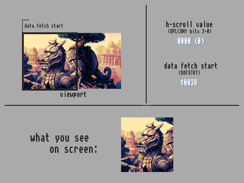
To scroll the bitmap horizontally, more legwork is required. First, you need to know that the video hardware fetches bitplane data word-by-word at the beginning of each scanline. The exact point where the data fetch should start, is determined by a value in a register called DDFSTRT. By modifying this register, we can start fetching an one word early, which effectively will shift the whole image by exactly 16 pixels.
That alone wouldn't let us achieve smooth horizontal scrolling, but here's where the BPLCON1 register can help us - it contains values that specify the horizontal viewport shift. Bits 3-0 control the shift value for one playfield, 7-4 for the second one, which gives us max 16 pixels per playfield to work with.
It may sound complicated on paper, but hopefully a visual presentation will make it easier to understand:
Summary
This was a rather theory-heavy post, but I hope it laid enough groundwork for us to actually be able to start the fun part - creating. :) The next post will be dealing with setting up our dev environment, getting familiar with the tools, the debugger, build system and the code structure of a typical demo effect. Stay tuned! ₍ ᐢ.ˬ.ᐢ₎
Additional resources
- "Amiga Hardware Reference Manual" - the holy book, I highly recommend reading it in the meantime
- "Produkcja demoscenowa 2021" [YT][PL] - recordings of a series of lectures I had a pleasure to attend in 2021. This is a source of most of my current knowledge. Sadly it's only available in polish and some recordings have ugly audio clipping.